Discover SAP EWM MFS
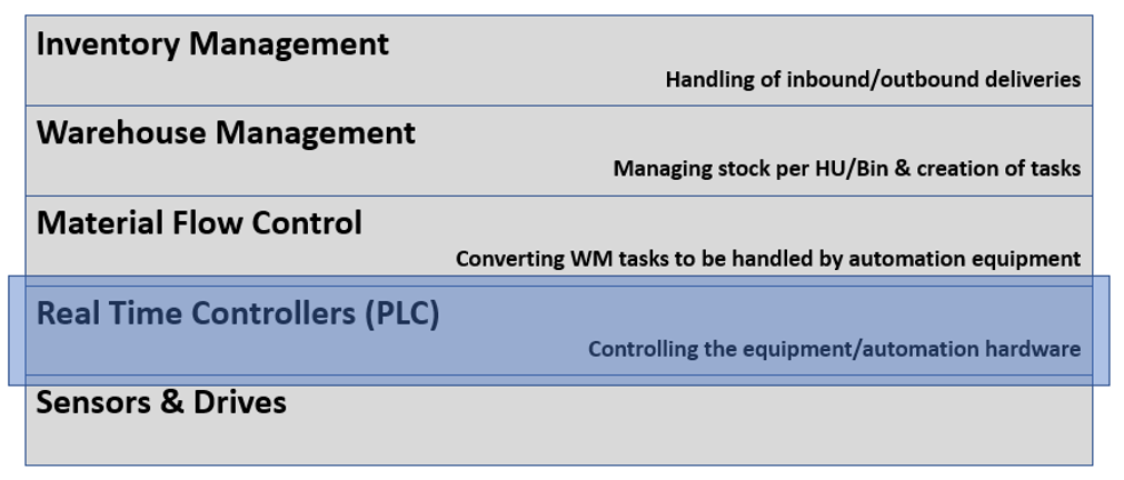
The role of the PLC
This blog is part of the series ‘SAP EWM meets Automation – Discover EWM MFS’ and gives you an introduction about the role of Programmable Logic Controllers (PLCs) as part of EWM MFS projects. I do think that Consultants & Developers involved in projects where the EWM MFS component is being used should at least have a high-level understanding of what a PLC is and what it is doing. This short article will provide exactly that level of detail that you need in order to grasp the end-to-end communication flows or in order to work together closely with the PLC-teams/programmers in such projects. Note that it is not intended to give an in-depth insight into how a PLC is constructed and how it is processing signals/data. Also note that there are special types of PLCs with technical variations which are not in-line with what I explain here. We ignore those specialties as the objective is to get a basic understanding of what a typical PLC is and does in an automated warehouse.
The content provided here has been created in cooperation with the SAP EWM team at Swisslog. Feel free to visit their website in case you want to learn more about the services offered by Swisslog or to browse open positions within their EWM team!
Agenda
– Main components of a PLC and their purpose
– Role of a PLC in the context of warehouse automation with SAP EWM
– Outlook
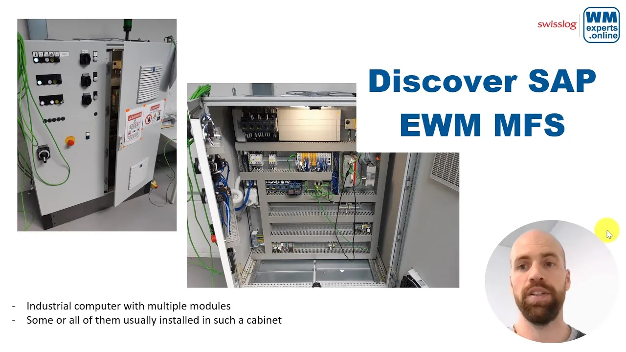
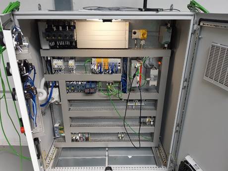
A PLC is a small industrial computer which consists of multiple modules. The main purpose – at least in our context – is to automize intralogistics processes. All or at least some of those modules are usually installed within such a cabinet:

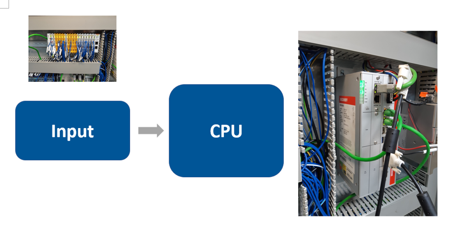
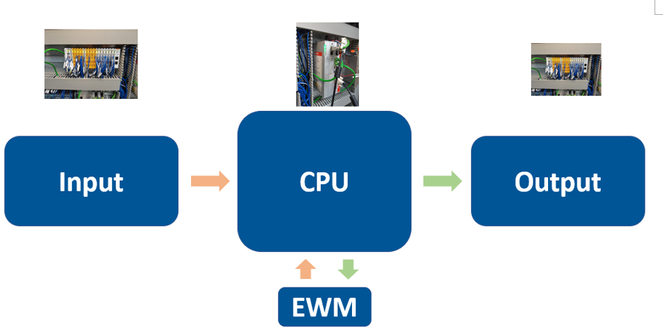
The most important modules are inputs/outputs as well as the CPU.
Input modules receive digital or analogue signals from multiple different sources (switches, sensors, scanners, light barriers etc.). Here an example of a case conveyor I-point with multiple different sensors & scanners. We come back to those input options later in this article:

The following pictures show examples of input/output modules were signals are received/send to/from the CPU:


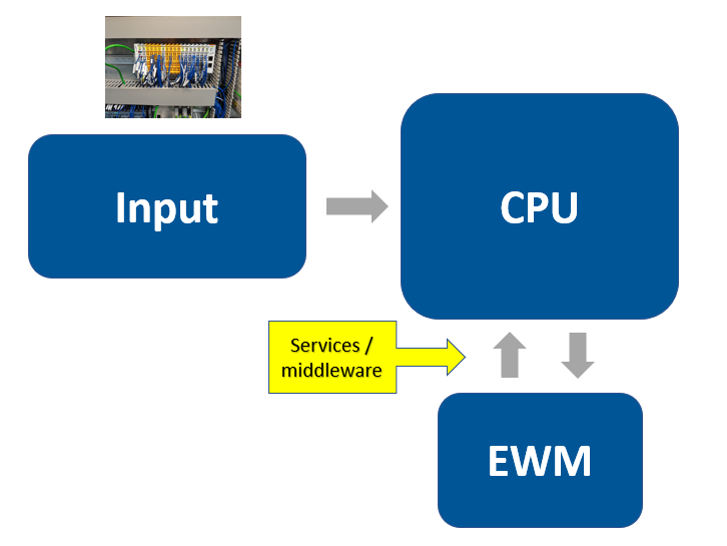
Note that it is not mandatory but you will sometimes see middleware/services running on servers in between the WMS and the PLCs which are e.g.
– determining the target PLC (e.g. in case relationship between logical PLC in EWM and physical PLCs is 1-n)
– converting the telegram format (e.g. in case different PLC vendors are connected to one WMS/protocol or in case RFC-TCP/IP converters like Plant Connectivity are being used instead of direct TCP/IP based communication via ABAP Push Channels).
The CPU is the heart of the PLC and it contains a memory which holds the program/coding which is responsible to process the input. The following picture shows a CPU produced by the company Beckhoff:

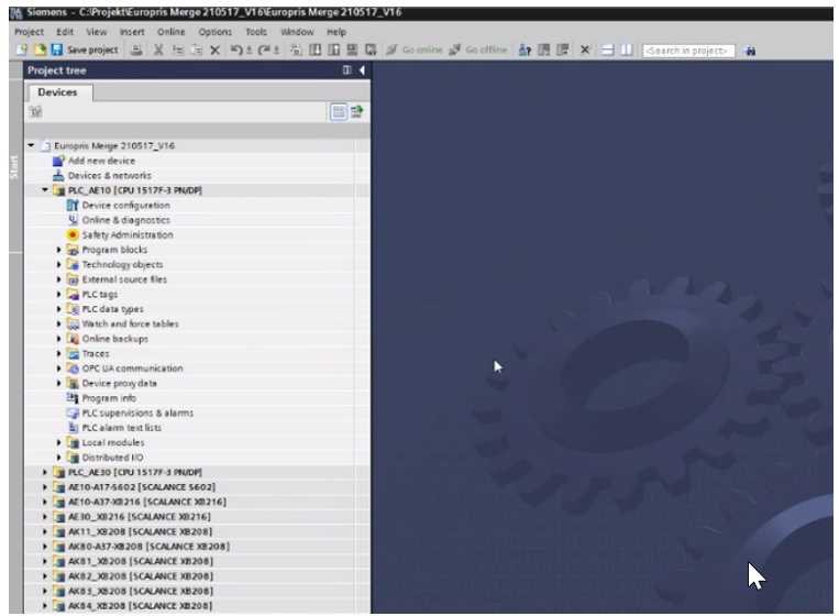
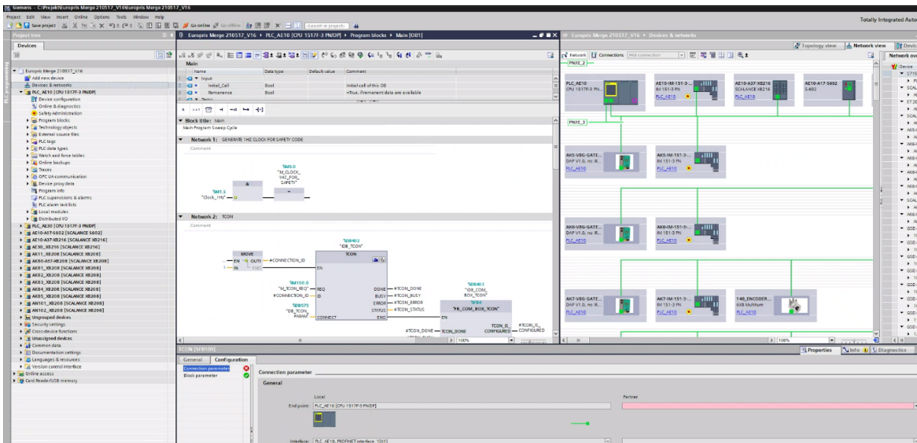
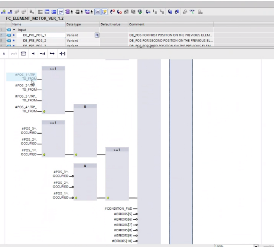
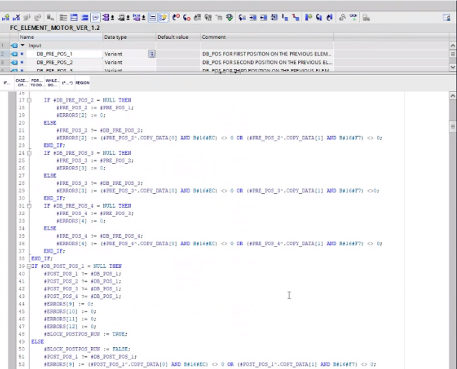
These programs are usually written in an application on a computer and then downloaded to the PLC. The TIA portal from Siemens is one example for such an application. It allows the engineer/developer to work with somewhat ‘simple’ logical operators but also complex coding, as shown in the screenshots below:
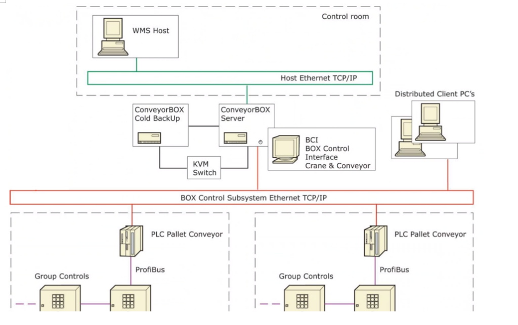
Input and output modules are connected to the CPU via bus systems or ethernet computer networks. Thus, the modules might be sitting in a shared cabinet (as shown in the pictures at the beginning of the blog/video) but could also be distributed across different buildings of the warehouse.
Summary of what the PLC does
1. Receive an input (~ monitor the status of multiple inputs)
2. Perform a logic using the inputs (e.g. connecting the inputs based on logical operators or use them as variables in a program)
3. Activate/deactivate outputs based on the results of the logic
That should be enough to give you a high-level understanding. Based on this, let us look at some practical examples from the warehousing world.
The role of the PLC in the context of warehouse automation
We start with simple examples for a pure PLC logic
1. Scanners: Activate a barcode scanner once a position/sensor is high which detects a pallet/HU at a scanner position

2. Conveyor engines: Start the conveyor once a pallet/HU is dropped on an infeed position


3. Position tracking: Pallet/HU moves from one conveyor segment to another conveyor segment > PLC receives input signals from the sensor(s) once the HU has left/arrived at a segment


Now some more complex examples where the PLC communicates with the underlying hardware as well as with EWM
1. I-Point pallet tunnel: Evaluate the status of the sensors which are installed for the tunnel check > send the result to EWM via telegram.

2. I-Point dimension check: Evaluate the status of the sensors which are installed to check the dimensions of the object > send the result to EWM via telegram

3. Crane movements: Create a stock removal task for a crane to remove a pallet from a bin in the given rack > start the motor to move the crane to the source position

To sum it up, in the context of warehouse automation the PLC is mainly responsible to
– monitor sensors to identify/track HUs
– control the drives for conveyors, cranes or other kind of equipment
– read the result of the scanners
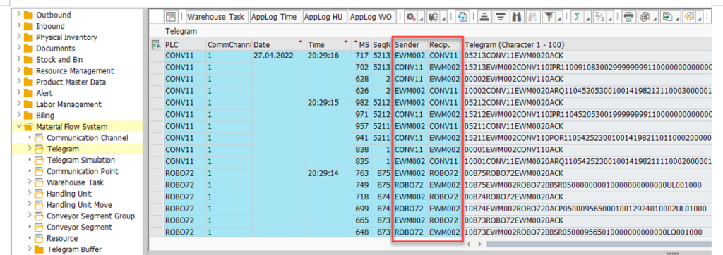
And as shown above, this interaction with the physics is then either an input to or an output of a pure PLC program logic or a logic which resides (partly/fully) in the WMS (e.g. SAP EWM) and is communicated from/to the PLC via telegrams.
Outlook
As mentioned at the beginning of this article, what you read here should serve as an introduction/basis for more complex articles which I will release during the next months. With the next post I will show you how EWM actually interlocks with the PLC before I provide a step-by-step overview of the communication from EWM to the PLC and the other way around.
And as as mentioned above, feel free to get in touch with the EWM team @ Swisslog in case you need support around MFS as part of your EWM projects! Browse through the open positions listed below, in case you are interested to join the team!
I hope this blog post provides value to you and you could learn something. Please feel free to subscribe to my blog updates or my youtube channel in case you want to be notified about new posts!
